
Over at eyetracktive.org you can see the results of some early experiments in creating the world’s most affordable eye tracking headset. The idea is to make this compatible with off the shelf google cardboard headsets.
One constantly underestimated problem, however, is that people have quite differently shaped heads, and eye positions. I find it obnoxious when we’re all forced to use a one-size-fits-all solution.
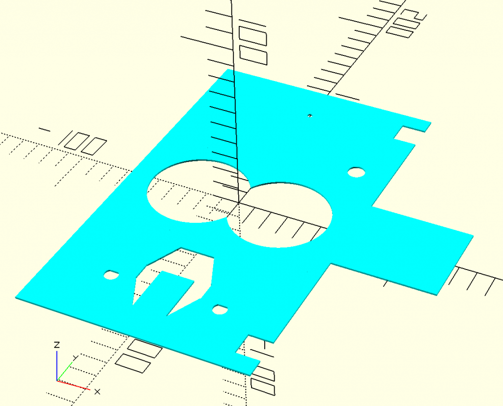
What I’ve been tinkering with for a while is an approach which uses OpenSCAD to “mathematically” define the headset parts (only the core which contains the eye tracking hardware so far, but soon, also the surrounding google cardboard design). The advantage of doing this in OpenSCAD is that all the critical dimensions can be defined as variables, with functions relating them in sensible ways to produce things like lines to cut! The even greater advantage of using OpenSCAD is that it can be called from the command line.
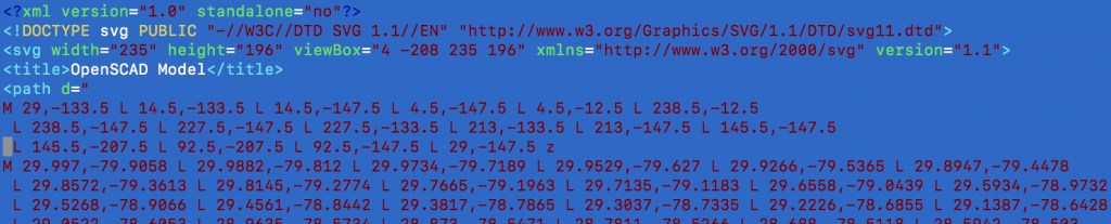
The idea that’s been waiting patiently for attention, for some time, is to setup a web service which takes customisation requests, passes them into the OpenSCAD model, and thereby produces an .svg as output . An SVG snippet might look something like this:
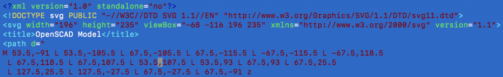
This scaleable vector graphics (SVG) file isn’t anything useful on its own – to have it turned into a laser cut piece of cardboard, we need to turn it into gcode. GCode is a simple language which tells motors where to move, and things like laser beams to turn on or off at a given power. Here’s a simple snippet of GCode with some comments as an example:
G28                //Move the head to home position
G1 Z0.0            //Move in a straight line to depth 0.0
M05                //Turn off the spindle (laser)
G4 P0.2            //Pause for little moment doing nothing
G0 X43.1 Y74.4     //Move rapidly to X/Y position
M03                //Turn on spindle (laser)
G0 X43.1 Y81.4     //Move rapidly to X/Y position
...and so on for hundreds and hundreds of lines
So, we want to get from an OpenSCAD description, to SVG, to GCode, and eventually, send that to a printer.
How hard can that be?!? Let’s knock up a prototype!
In practice, I have no idea what machine I will ultimately connect to my super cheap Eleksmaker A3 Pro laser cutter -> but I know that it’ll either be one of the several linux or osx machines I have knocking around- so lets pick an approach which will work just as well on any of them. One approach which will do for us is called Docker.
Docker basically packages everything an application needs to run into what they call a container. From the point of view of the application, it feels and looks like it is running in an operating system on a computer dedicated to nothing but keeping it happy and running perfectly. In actual fact Docker is just using smoke and mirror to make it look this way – but it’s a trick which Docker have perfected on pretty much every computing platform, so it’s really containerise once, run anywhere 😉
First we knock up a Dockerfile (thanks to @mbt for getting the ball rolling!) containing what we want in our environment. The most important parts are openscad and py-svg2gcode (which does the .svg to .gcode conversion). We then start the container :
docker run -i -t -v [host path]:/tmp/[something] openscad bash
This starts an interactive container, dumping us into bash, with [host path] mapped from the host machine to /tmp/[something] inside the docker container.
When we try to run py-svg2gcode, the first thing we notice are a bunch of errors :
Yippee. Nothing ever works first time. Actually, this isn’t so bad. “ValueError: invalid literal for float(): 210mm” is perhaps a little cryptic at first sight, but it’s actually probably indicating that it is expecting a floating point number, where it is receiving a string containing “mm”. Low and behold, if you look at the snippet of .svg above, you’ll see this is precisely what is happening.
Before we run svg2gcode, let’s always replace any occurrences of “mm” in incoming .svg files! Perhaps we’ll call svg2code from a bash script which preprocesses with :
sed -i ‘s/mm//g’ $1
This takes the input argument to the script ($1) as a filename to process, then uses the unix command sed to find all instances of mm (the g) and replace them in the same file (-i) with, well nothing!
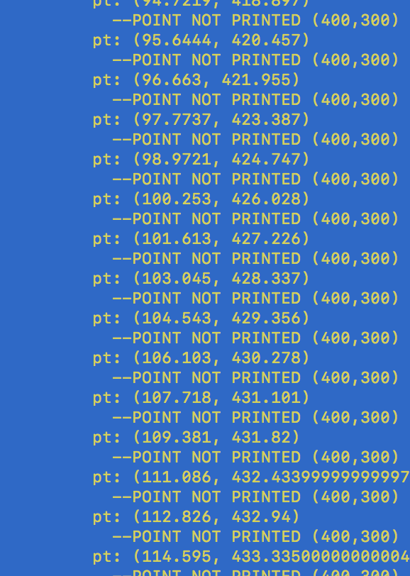
Great. Our next inevitable problem is that we get a load of these statements in the output :
Perhaps the point -17/97 is somehow outside the bounds of the printer? It turns out that svg2gcode uses a config.py to define constants such as the area of the printer. Indeed, bed_max_x and bed_max_y are both set to 150. We’ll have to change that, and do it in a way that Docker remembers between restarts. We’ll also have to worry about why we’re getting negative values in just a moment. Is the problem that the point is negative, or that the cumulative y position to date exceeds 150?
First of all, in our Dockerfile we can tell it to take a file from our local file system and add it to the Dockerfile:
COPY config.py /py-svg2gcode/config.py
Now we have :
pt: (-28.0079, 217.75119999999998)
–POINT NOT PRINTED (400,300)
So more points got printed, but the negative numbers are clearly a problem. This may mean we need to be careful in generating our coordinate space, or we cheat, setting the origin of the laser cutter to the middle of its area and defining the available space as -200 to +200 and so on…
Looking in the OpenSCAD file I am trying to convert, and there we are… the headset is centered around the origin.
For now I shall apply a transform to shift it off origin before we attempt the gcode generation:
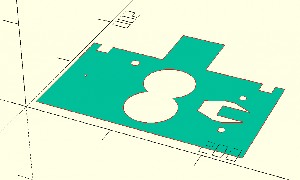
When we inspect this in Inkscape, it also looks good:
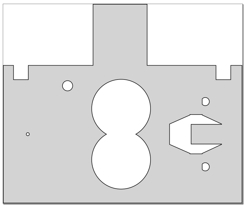
..and in the raw .svg we see that the width and height are within the bounds of our machine:
None of the points in the line description exceed either width or height. You’d think this would be fine for svg2gcode, right?
Sigh. Pages and pages of “point not printed” :
After then looking into svg2gcode.py I’ve realised it looks quite incomplete, and makes many strange assumptions about scaling etc. which don’t fit our use case. Time to try a different approach….
OpenSCAD supports DXF export, and there appears to be a more mature dxf2gcode library out there – so let’s go with the flow and try taking that approach instead!.. only after updating my container to install it, it turns out that this isn’t a library, it’s a program that requires a window manager… and so it goes on. This is the reality of prototyping, as you cast around for tools to do the job in the vain hope that you’re not going to have to end up implementing too much yourself. :-/
It feels like options are running out – should I take a look at https://sourceforge.net/projects/codeg/? – a project that stopped doing anything back in 2006. All in all this is terribly sad for such a basic and common (?) need. Perhaps first it’s time to look more deeply at svg2gcode.py and see if we can just strip out its weird scaling code.
First off, it actually looks like there are many branches of the original code – for example – https://github.com/SebKuzminsky/svg2gcode is more up to date than most. Let’s update our Dockerfile in a way you never would in production to try things out quickly:
Now we’ll build our new container with :
Now let’s have an initial nose around. At first glance, this looks way more intense – there’s a lot of code in the svg2gcode.py specifically for milling. It’s a different kind of beast to the last python script! Taking a look in the README.md (why don’t I ever think to start there) says that it can handle engraving. How can we specify that type of operation?
“python svg2gcode” actually gives us some sensible feedback/potential instructions. I’m already liking this – although I see no options for “engraving/offset/pocket/mill” and so on. Let’s take another look in the .py file.
So – I’m not a python guy *at all* but :
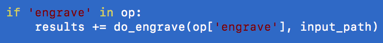
…but what are these op operations it speaks of? It looks like there is some sort of json formatted job descriptions. Not sure I like the way *that* is going. Also, some interesting leads in https://github.com/SebKuzminsky/svg2gcode/blob/master/TODO.adoc.
Yep. A quick “grep -R engrave *” reveals a bunch of unit tests (it’s back in my good books again) which show a job format xxx.s2g in json that looks like :
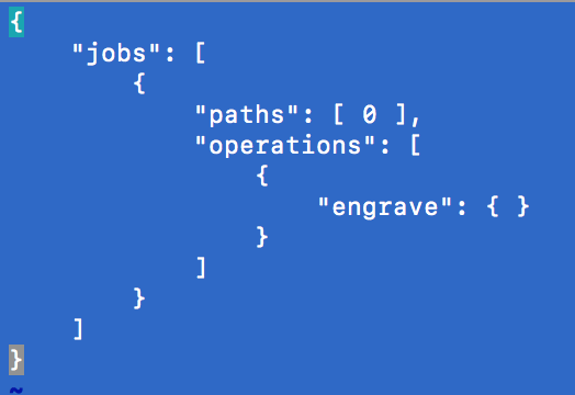
so, it looks like we need a job description, next to our svg – and we can see what comes out of it!
Here’s the output:
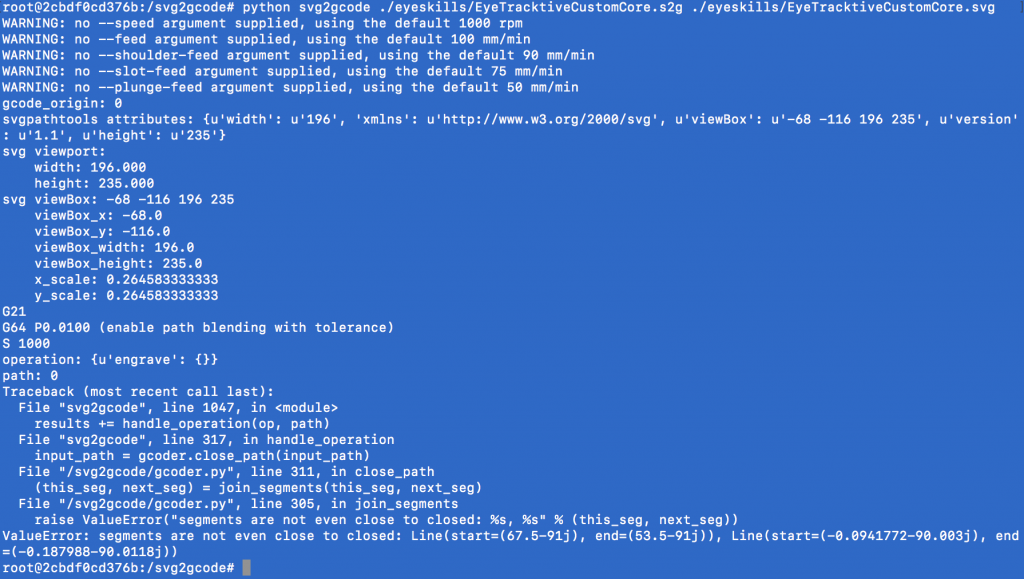
So, it doesn’t like the paths in the .svg. Why? That’s the next thing to explore. I’ll output some simple primitive shapes in OpenSCAD, then some using operations like “difference” and see when/where the conversion process breaks…. or this is a deeper problem? Do I need to create many jobs composed of much lower level “closed” lines?
Yep. Looking at some of the more advanced examples with multiple shapes in the .svg the job description defines how each individual path needs to be handled :
This is well beyond what we want or need. It is a general artefact of abstraction that the more generic a tool becomes, the harder it is to get it to do anything specific. A theory of the universe just wraps the universe in a plastic bag and you’re no closer to understanding any of it.
My gut feeling tells me, go back to the cruder and simpler original svg2gcode.py and modify. Our needs are simple.
Well, that’s another 40minutes an evening gone. Back at it at the next opportunity!